What is a Strain Gauge Where: A
Wheatstone bridge is an electrical circuit used to measure an unknown electrical
resistance by balancing two legs of a bridge circuit. The Wheatstone bridge
consists of four resistances (R1, R2, R3 and R4), an excitation voltage and an
output voltage. Generally, one or more of the resistances are variable and
change in accordance with some physical phenomenon, such as strain in this case.
The Wheatstone bridge then converts this change in resistance to a change in
voltage. There are 3 configurations are used - quarter bridge,
half bridge or full bridge. Full Bridge Circuit: Connect Strain Gauge
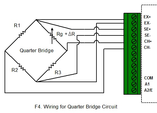
to a Data Logger Wiring for Quarter
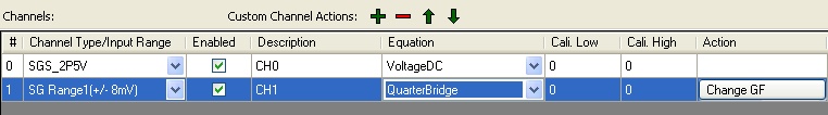
Bridge Circuit: This circuit is for equation QuarterBridge. When
configure the logger, choose QuarterBridge equation and click Change GF to
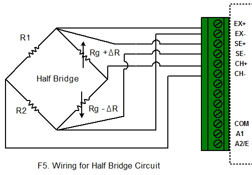
change the Gauge Factor. Wiring for Half Bridge
Circuit: This circuit is for equation HalfBridge. When
configure the logger, choose HalfBridge equation and click Change GF to
change the Gauge Factor. Wiring for Full Bridge
Circuit: This circuit is for equation FullBridge. When
configure the logger, choose FullBridge equation and click Change GF to
change the Gauge Factor. Other Bridge Circuit: // Sample Equation for iLog Strain
Gauge/Bridge public double SampleBridge(double
Input) {
//Change it according to your curcuit
double
GF = 1;//Gauge
Factor
//The voltage of the bridge output
double Vo =
Input;
//The voltage of the Excitation sense channel
double Vex =
Channels[0].Measurement;
/* this block is for half bridge circuit
double strain = -2 * Vo / (Vex * GF);
return strain;
*/
/* this block is for full bridge circuit
double strain = -Vo / (Vex * GF);
return strain;
*/
/* this block is for quarter bridge circuit */
double strain = -4 * Vo / ((2 * Vo
+ Vex) * GF);
return
strain; }
A strain gauge (also strain gage)
is a device used to measure the strain of an object.
The gauge is attached to
the object by a suitable adhesive. As the object is deformed, the foil is
deformed, causing its electrical resistance to change. This resistance change,
usually measured using a Wheatstone bridge, is related to the strain by the
quantity known as the gauge factor.
The gauge factor GF is defined as: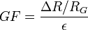
?R is
the change in resistance caused by strain is the resistance of the undeformed
gauge, and e
is
strain.
is the resistance of the undeformed
gauge, and e
is
strain.
Only one active strain gauge (Rg) is used as shown below.
R3 is the inactive gauge, which is identical to the active gauge but does not
encounter any mechanical strains and is used for compensating the temperature
effect. The other two arms contain fixed resistors.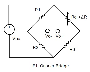
If the dummy gauge in the above figure is replaced by an
active gauge, as shown below, the resulting arrangement is called a half bridge.
The half bridge has advantages for temperature compensation and higher bridge
sensitivity over the quarter bridge so that small strain levels can be detected
more accurately.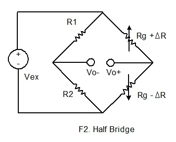
If
four active gauges are employed in the circuit, the arrangement is called Full
Bridge as shown below. It is automatically temperature compensated when
all four active gauges bonded on the same material, and the highest sensitivity
is obtained.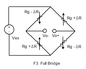
iLog Srtrain Gauge/Bridge data
logger supports six-wire configuration when connecting to a wheatstone bridge
circuit. The following wirings are for SiteView built-in Strain Gauge
equations:

If your
bridge circuit is not included in the above configurations, you may need to
write your own equation. SiteView includes a custom equation BridgeSample
for your reference. The source code looks like: