
LPSE-1 SITE-LOG Pulse/State/Event Data Logger

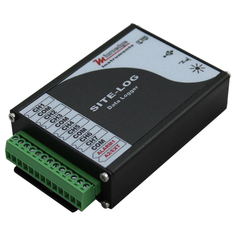
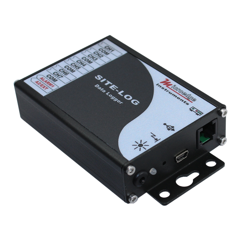
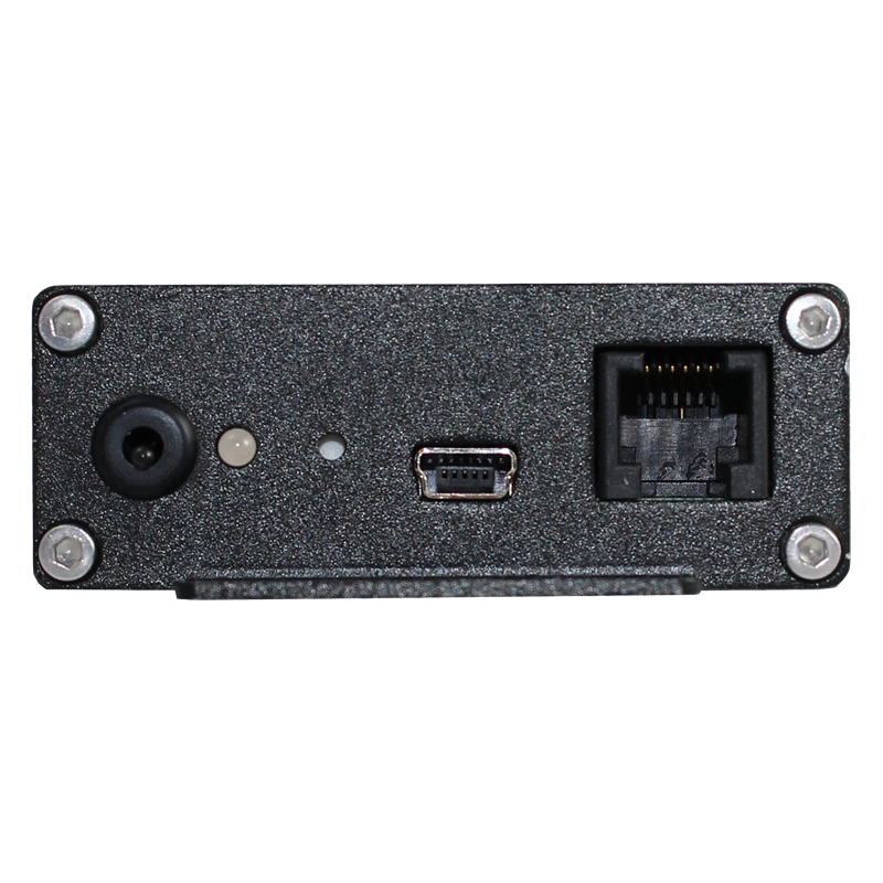
The SITE-LOG LPSE-1 is a 7-channel, battery-powered, standalone pulse, state, and event data logger designed for monitoring pulse outputs, digital signals, switch closures, equipment states, and event changes.
Each of the seven external input channels can be independently configured as a:
- Pulse input
- State input
- Event input
This flexible channel configuration combines the functions of pulse counters, state loggers, and event recorders in a single compact instrument.
The LPSE-1 can be used with:
- Gas meters
- Water meters
- Power meters
- Rain gauges
- Flow meters
- Equipment status contacts
- Relay outputs
- Solid-state switches
- Dry contacts
- TTL digital signals
- Other compatible pulse or switch-closure devices
Recorded data is stored in 8 MB of non-volatile flash memory for later retrieval.
Its rugged aluminum enclosure and conformal-coated circuit board make the LPSE-1 suitable for industrial, laboratory, research, equipment-monitoring, and field applications.
Flexible Pulse, State, and Event Inputs
Each of the seven channels can be independently configured through software for Pulse, State, or Event operation.
Supported input types include:
- Voltage signals
- Solid-state switches
- Coil relays
- Dry contacts
- TTL digital signals
For Pulse and Event configurations, each channel's trigger detection can be configured as:
- Normally Open: High-to-Low transition
- Normally Closed: Low-to-High transition
A software-configurable 100 kΩ internal pull-up resistor is also provided to simplify connection to switches, contacts, and compatible digital-output devices.
Pulse Counting and High-Speed Operation
The LPSE-1 supports pulse counting for metering, flow monitoring, equipment-cycle counting, and similar applications.
When operating from the internal battery:
- Up to 10 Hz with multiple channels enabled
- Up to 20 Hz when only one channel is enabled
- Minimum detectable pulse width: 35 ms
When externally powered:
- Up to 2 kHz with multiple channels enabled
- Up to 4 kHz when only one channel is enabled
- Minimum detectable pulse width: 0.5 ms
Each sampling interval can record up to 65,535 pulse counts, with an accuracy of ±1 pulse.
Standalone Operation and Long-Term Recording
Once configured, the LPSE-1 operates independently without requiring a continuously connected computer.
Recorded data is stored in 8 MB of onboard non-volatile flash memory for later retrieval.
Logging intervals are programmable from:
1 second to 12 hours
Logging can be activated by:
- Immediate start
- Programmable delayed start
- Field push-button activation
When memory becomes full, the logger can be configured to:
- Stop recording, or
- Continue recording in FIFO mode
The internal lithium battery provides up to approximately 5 years of operation at a 1-minute sampling interval in standalone mode, depending on operating conditions and configuration.
USB Communication and SiteView Software
The LPSE-1 connects directly to a Windows PC through its Plug & Play USB interface.
SiteView software provides tools for:
- Configuring Pulse, State, and Event channels
- Selecting channel trigger conditions
- Setting logging intervals
- Configuring logging sessions
- Downloading recorded data
- Viewing real-time information
- Displaying recorded data
- Plotting and analyzing data
- Configuring alarm thresholds
- Applying custom calibration
- Applying custom equations
- Converting recorded values into engineering units
The LPSE-1 also provides an AUX TTL-level serial communication interface, with automatic baud-rate detection from 2400 to 115200 bps.
Alarm and Excitation Control
The LPSE-1 provides configurable alarm and control functions for applications requiring more than basic data recording.
Each channel supports two programmable alarm thresholds.
The available output terminals can be configured for:
- Alarm output
- Excitation control
The onboard status LED provides visual indication of normal sampling, alarm conditions, and low battery status.
Remote SiteView Access through Smart-Hub
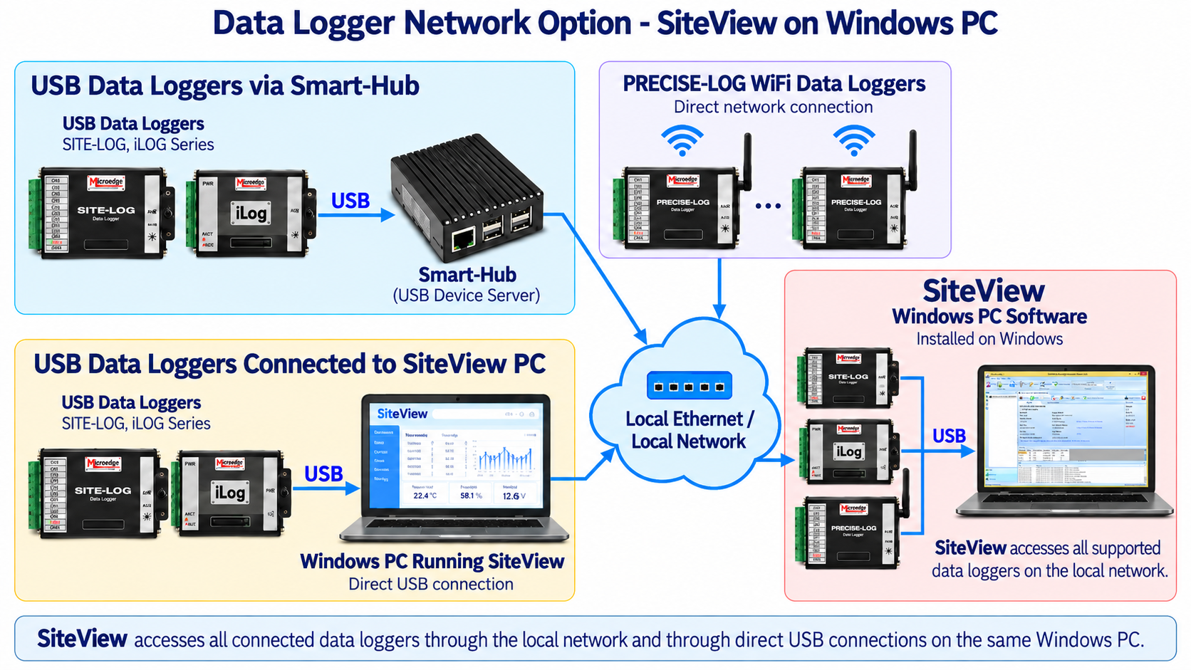
The LPSE-1 can be connected to a Microedge Smart-Hub for remote access over an Ethernet network.
Smart-Hub operates as a USB Device Server, allowing SiteView running on a Windows PC to remotely access an LPSE-1 connected to the Smart-Hub's USB port.
This allows SiteView to communicate with the LPSE-1 over the local network without requiring the logger to be directly connected to the SiteView PC by USB.
Network Compatibility
- Direct USB connection to SiteView: Supported
- Smart-Hub USB Device Server: Supported
- SiteView through Smart-Hub: Supported
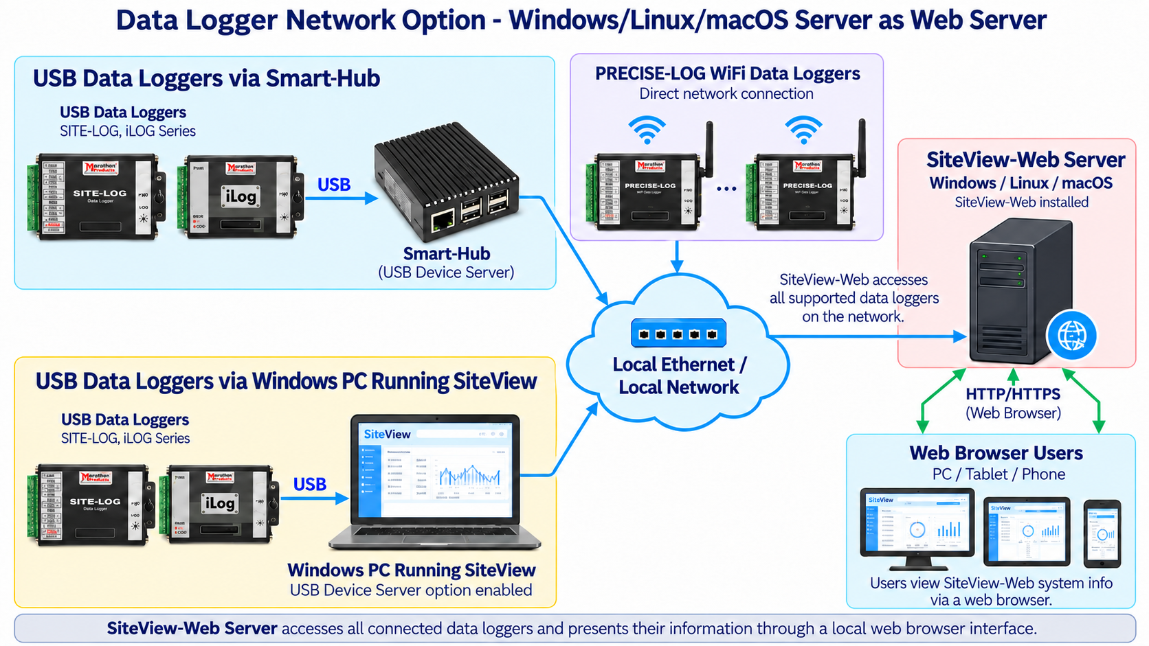
- SiteView-Web: Not supported
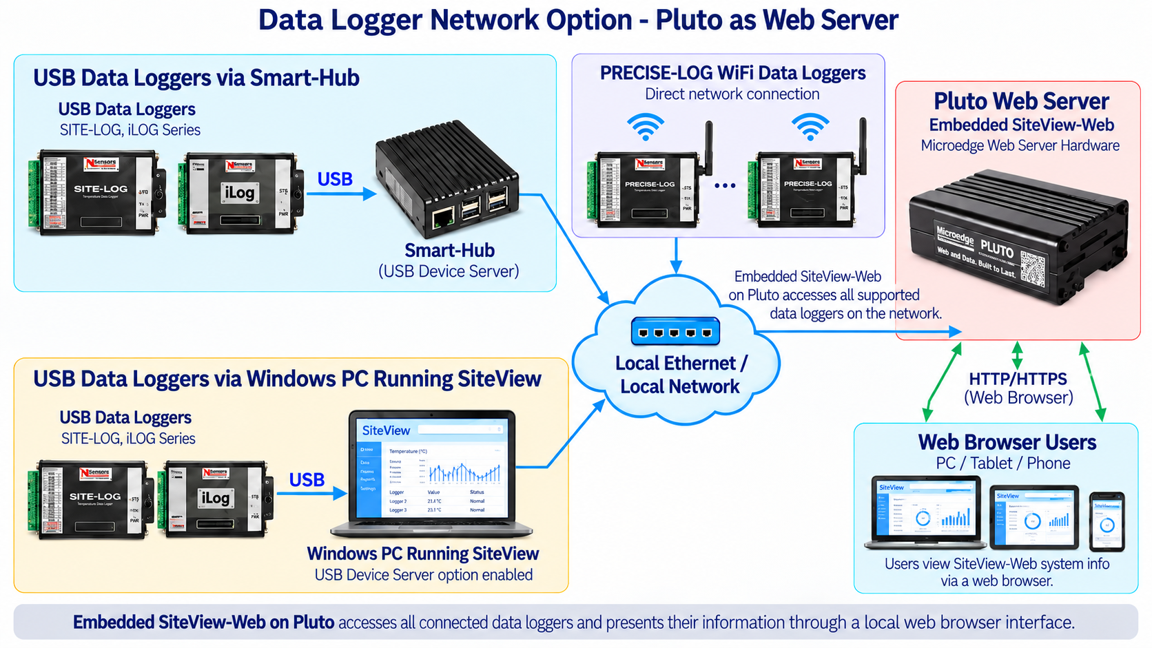
- Pluto: Not supported
Rugged Industrial Design
The LPSE-1 is housed in a durable aluminum enclosure.
Its circuit board uses a conformal coating to provide additional protection against:
- Moisture
- Corrosion
- Mildew
The logger is designed for operation from:
−40°C to +70°C (−40°F to +158°F)
and:
0–95% RH, non-condensing.
KEY FEATURES
7 Independent Input Channels
Each external channel can be independently configured as a Pulse, State, or Event input.Pulse, State, and Event Recording
Combines the functionality of three types of digital-input loggers in one compact unit.8 MB Non-Volatile Flash Memory
Provides long-term onboard storage for recorded data.Flexible Digital Inputs
Supports voltage signals, solid-state switches, coil relays, dry contacts, and TTL digital signals.Configurable Trigger Detection
Pulse and Event channels can be configured for High-to-Low or Low-to-High transitions.Software-Configurable Pull-Up
A 100 kΩ internal pull-up resistor can be enabled or disabled through software.High-Speed Pulse Counting
Supports pulse rates up to 2 kHz with multiple channels or 4 kHz with one channel when externally powered.Wide Logging Interval Selection
Programmable from 1 second to 12 hours.Flexible Logging Modes
Supports immediate start, delayed start, field push-button activation, stop-on-full, and FIFO operation.USB Communication
Plug & Play USB communication provides direct connection to SiteView.TTL-Level Serial Communication
AUX communication interface supports automatic baud-rate detection from 2400 to 115200 bps.SiteView Software Support
SiteView provides configuration, data download, real-time viewing, plotting, analysis, custom calibration, custom equations, and alarm configuration.Alarm and Excitation Control
Supports programmable alarm thresholds and configurable alarm/excitation outputs.Remote SiteView Access through Smart-Hub
LPSE-1 can connect to Smart-Hub and use its USB Device Server functionality, allowing SiteView to access the logger remotely over Ethernet.Long Battery Life
Provides up to approximately 5 years of operation at a 1-minute logging interval in standalone mode.Rugged Aluminum Enclosure
Designed for laboratory, industrial, and field environments.Conformal-Coated PCB
Helps protect against moisture, corrosion, and mildew.
TYPICAL APPLICATIONS
The LPSE-1 is suitable for:
- Pulse counting
- Water meter monitoring
- Gas meter monitoring
- Power meter monitoring
- Flow meter monitoring
- Rain gauge recording
- Equipment cycle counting
- Equipment operating-state monitoring
- Pump and motor status monitoring
- Relay-state monitoring
- Dry-contact monitoring
- Switch-closure recording
- Digital event recording
- TTL signal monitoring
- Industrial equipment monitoring
DOCUMENTS
| General | |
|---|---|
| Product Name | SITE-LOG 7-CH Pulse/State/Event Data Logger |
| Model | LPSE-1 |
| Inputs | |
| Channels | 7 external channels |
| Channel Configuration | Each channel can be independently configured as Pulse, State, or Event |
| Connection | Pluggable terminal block for seven external channels, excitation control, and alarm outputs |
| Input Types | Voltage, solid-state switch, coil relay, dry contact, TTL digital signal |
| Maximum Pulse Count per Interval | 65,535 counts |
| Pulse Accuracy | ±1 pulse |
| Internal Pull-Up | 100 kΩ, software configurable |
| Input Impedance | ≥1 MΩ |
| Maximum Input Voltage | 40 V |
| Trigger High Voltage | ≥2.7 V |
| Trigger Low Voltage | ≤0.5 V |
| Pulse Performance | |
| Max. Pulse Rate | Without external power supply: 10 HZ (20 HZ if only one channel enabled) With external power supply : 2 KHZ (4 KHZ if only one channel enabled) |
| Min. Pulse Width | Without external power supply: 35 milliseconds With external power supply: 0.5 milliseconds |
| Trigger Configuration | |
| Trigger Mode | Detection |
| Normally Open | High-to-Low transition |
| Normally Closed | Low-to-Hightransition |
| Alarm Functions | |
| Channel Alarm Thresholds | Two programmable alarm thresholds per channel |
| Alarm Outputs | ALARM1 and A2/E terminals can be configured as alarm outputs |
| Alarm Output Type | N-channel MOSFET switch |
| Alarm ON | MOSFET switch ON |
| Alarm OFF | MOSFET switch OFF |
| Maximum Alarm Output | 200mA @ 24 VDC |
| Alarm Delay | Programmable from 0 to 10 minutes in 1-minute increments |
| Alarm Indicator | Status LED flashes red during sampling when an alarm condition is active |
| On-board Memory | |
| Flash Memory | 8 MB (4MB readings) non-volatile flash memory |
| Data Retention | More than 20 years. |
| Memory-Full Options | Stop logging or FIFO mode |
| Sampling and Logging | |
| Sampling Interval | Programmable from 1 second to 12 hours |
| Logging Modes | Stop when memory is full or continue in FIFO mode |
| Logging Activation | Immediate start, delayed start, or field push-button activation |
| Communications | |
| USB Interface | Mini-USB-B |
| USB Cable | USB-A to Mini-USB-B cable included |
| AUX Interface | RJ11 TTL level serial communication |
| Baud Rate | Automatically detected from 2400 to 115200 bps on USB and AUX interfaces |
| Remote Network Access | Available through Microedge Smart-Hub |
| Battery and Power | |
| Internal Battery | Built-in 3.6V Lithium Battery. |
| Battery Life | Up to 5 years at a 1-minute sampling interval, depending on usage and operating conditions |
| External Power | 5 VDC through USB |
| Software | |
| Software | SiteView (Sold separately) |
| Functions | Logger configuration, data download, graphing, real-time monitoring, custom calibration, custom equations, alarm configuration, and data analysis |
| Operating Systems | Windows 8, 10 and 11 |
| Computer Requirement | 1.0 GHz or faster processor; 1 GB RAM or higher; 10 GB available storage or higher |
| Required Interface | At least one available USB port |
| Physical Specifications | |
| Enclosure Material | Aluminum |
| PCB Protection | Conformal coating. |
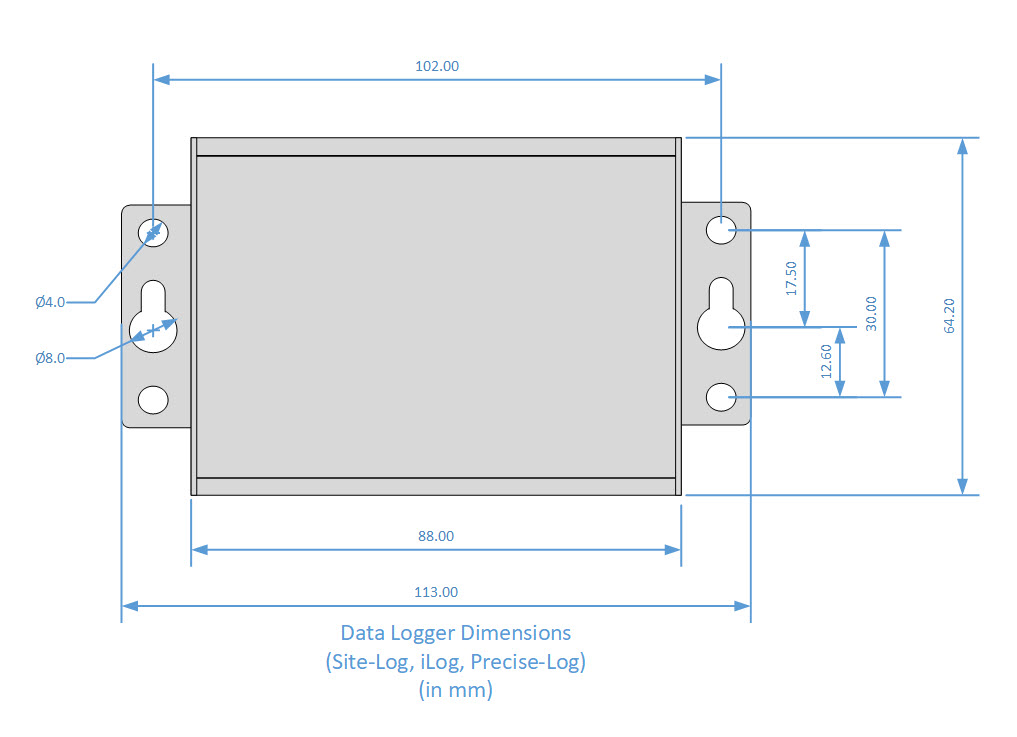
| Dimension | 88 X 64.2 X 24 mm (3.46 X 2.53 X 0.95 inches) |
| Weight | 200g |
| Mounting | Integrated holes for wall or equipment mounting |
| LED Indicators | |
| The tri-color status LED can be disabled to reduce power consumption. | |
| Green Indication | Normal sampling |
| Red Indication | Alarm condition |
| Amber Indication | Low battery |
| Excitation Control | |
| The A2/E terminal can be configured as an excitation-control output for controlling power to an externally powered sensor or device. The excitation warm-up delay is programmable from: 10 to 240 seconds in 10-second increments | |
| Operating Environment | |
| Operating Temperature | -40 ~ +70 °C (-40 °F ~ 158 °F) |
| Operating Humidity | 0 ~ 95% RH, non-condensing |
| Clock Accuracy | ±1 mintue per month |
| Approval | CE, FCC |
Logger Memory Capacity
| Sampling Interval | Enabled Channel | Logging Capacity |
|---|---|---|
| 1 minute | 1 | 484 days |
| 1 minute | 7 | 69 days |
| 10 seconds | 1 | 80 days |
| 10 seconds | 7 | 11 days |
| 1 second | 1 | 8 days |
| 1 second | 7 | 27 hours |
Note: For State and Event channel, the above capacity is calculated based on a state or event occurs in every sampling period.
Resources: