
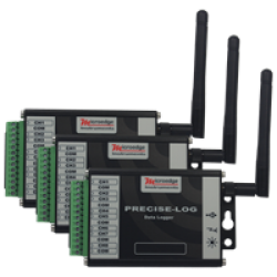

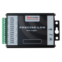
PL-HW PRECISE-LOG 8-Channel WiFi Thermistor Data Logger
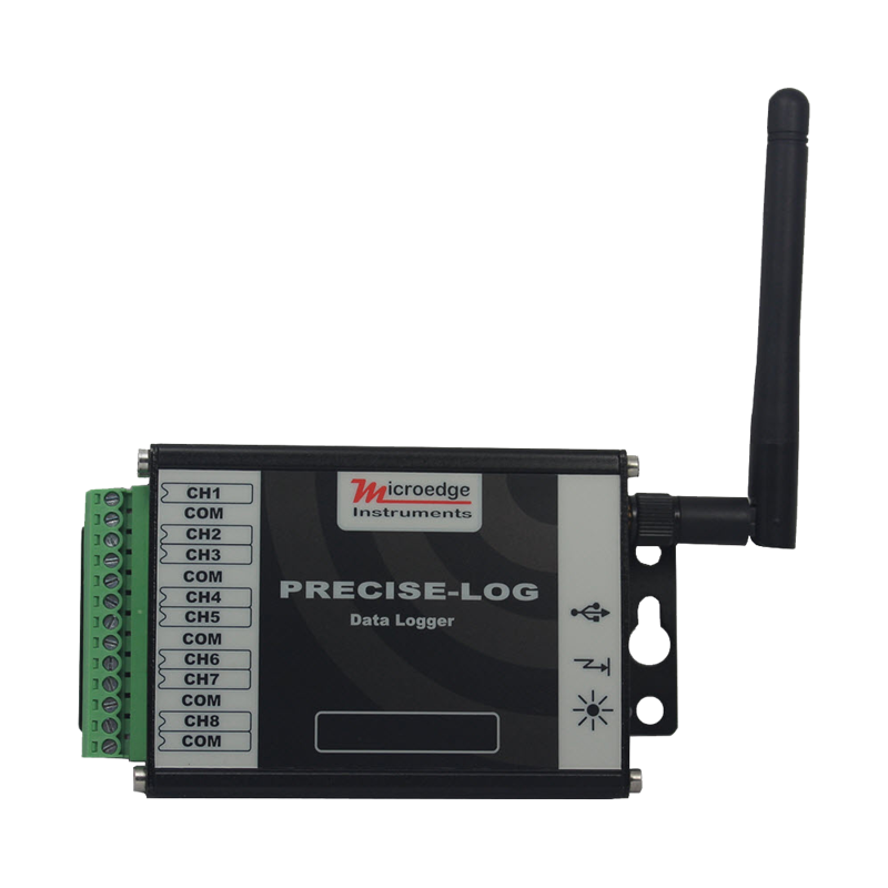
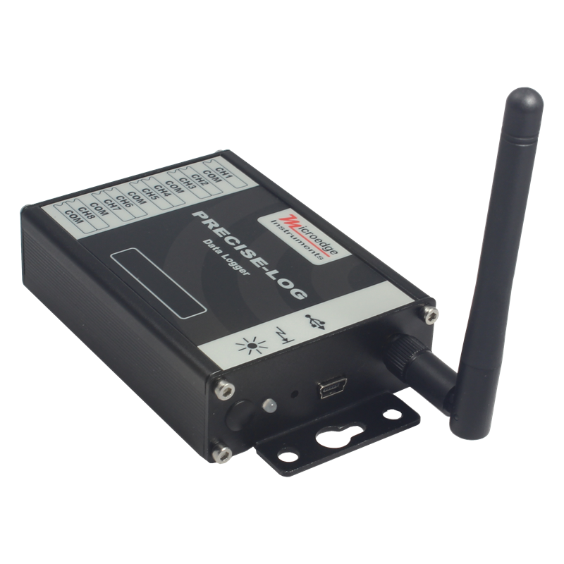
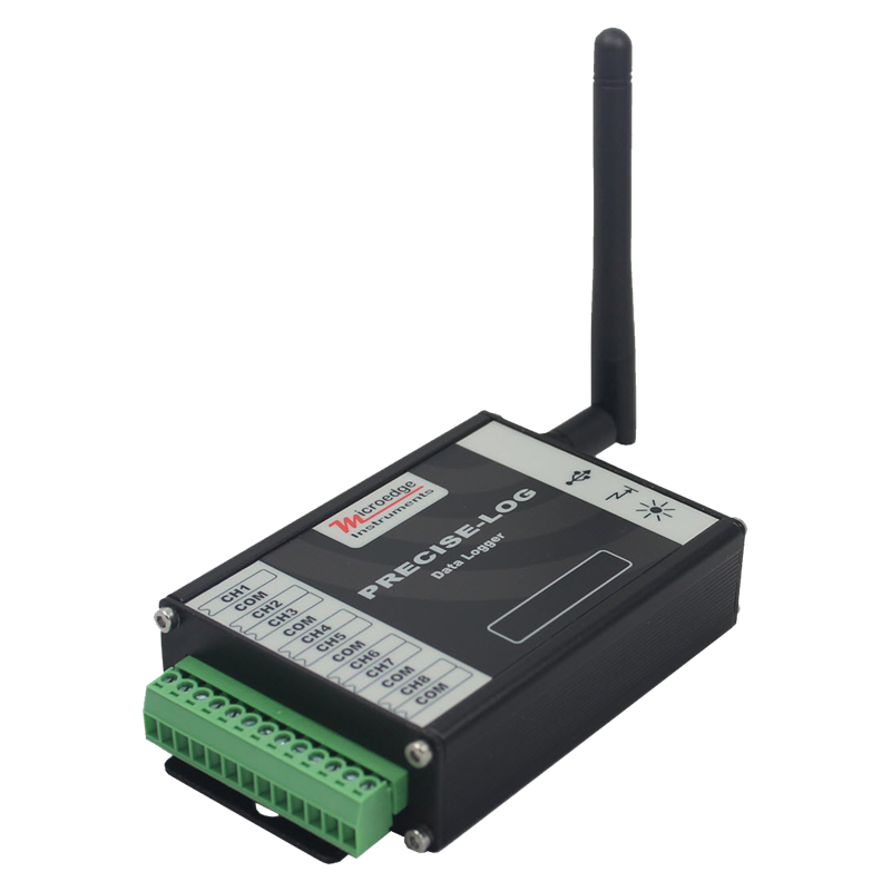
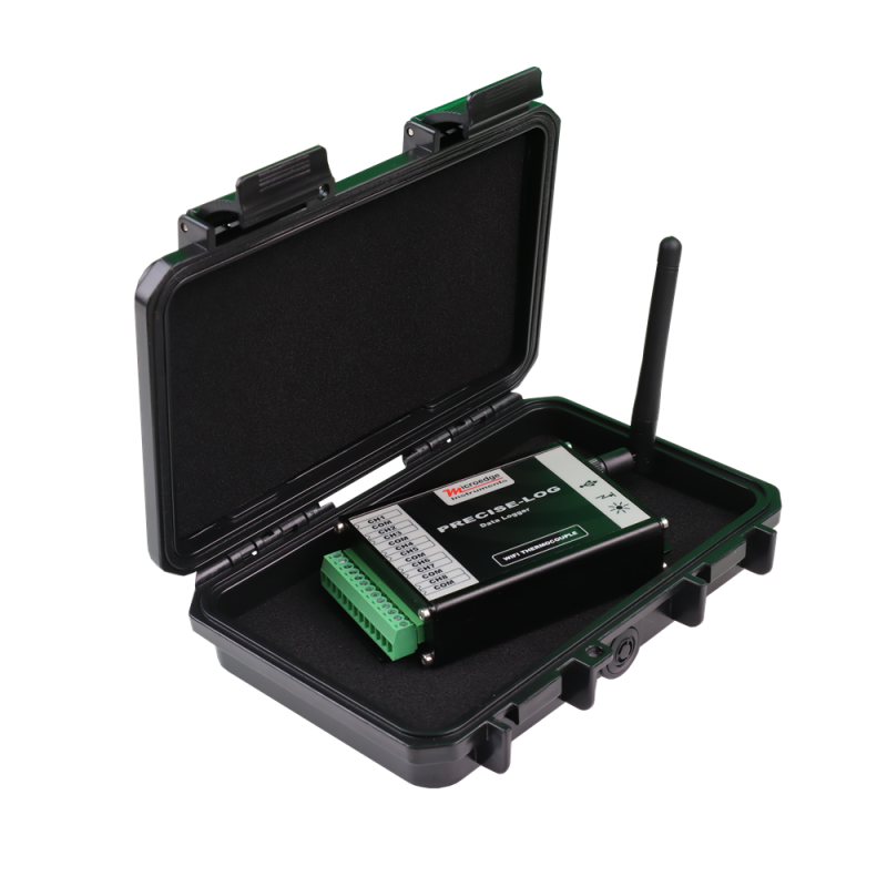
The PRECISE-LOG PL-HW is an 8-channel, battery-powered, standalone and WiFi-enabled thermistor and resistance data logger designed for industrial, laboratory, research, testing, and remote temperature-monitoring applications.
The logger provides:
- 8 external thermistor / resistance input channels
- 16-bit measurement resolution
- USB and WiFi communication
- 8 MB non-volatile flash memory
- Direct Modbus TCP support
- Long-term standalone operation
PL-HW is optimized for temperature measurement using compatible thermistors, including commonly used 10 kΩ NTC thermistors.
Each channel can be independently enabled and configured through SiteView.
Because WiFi is built directly into the PL-HW, the logger can connect to a local wireless network without requiring Smart-Hub or another external USB Device Server.
Multi-Channel Thermistor and Resistance Measurement
The PL-HW provides eight external input channels for simultaneous thermistor or resistance measurement.
It is well suited to multi-point temperature-monitoring applications using compatible NTC thermistors.
For a 10 kΩ NTC thermistor, the published logger accuracy is:
±0.2°C from 0°C to 70°C
This value does not include the accuracy of the thermistor probe itself.
The PL-HW can also provide resistance readings, allowing compatible resistive sensors to be used with appropriate SiteView equations or calibration.
High-Resolution Data Logging
The PL-HW uses a 16-bit analog-to-digital converter with a measurement resolution of:
0.0018%
This provides high-resolution resistance and thermistor measurements for laboratory, industrial, research, validation, and testing applications.
Standalone Operation and Long-Term Recording
The PL-HW operates independently after configuration and stores measurements in 8 MB of non-volatile flash memory.
The memory provides storage for approximately 4 million readings and retains recorded data for more than 20 years.
Logging can be configured for:
- Immediate start
- Delayed start
- Field push-button activation
When memory becomes full, the logger can either:
- Stop recording, or
- Continue recording in FIFO mode
The built-in 3.6 V lithium battery provides up to approximately 10 years of operation at a 1-minute sampling interval in standalone mode, depending on operating conditions and configuration.
USB and WiFi Communication
The PL-HW provides both USB and WiFi communication.
USB can be used for direct local communication with SiteView.
The built-in WiFi interface allows the logger to connect directly to a local wireless network for remote access.
WiFi can be enabled or disabled through SiteView.
SiteView Software
The PL-HW is supported by SiteView software.
SiteView provides tools for:
- Configuring thermistor / resistance channels
- Configuring logging sessions
- Downloading recorded data
- Viewing real-time temperatures or resistance values
- Displaying graphs and tables
- Configuring alarm thresholds
- Applying custom calibration
- Applying custom equations
- Converting resistance measurements into engineering units
- Exporting and analyzing recorded data
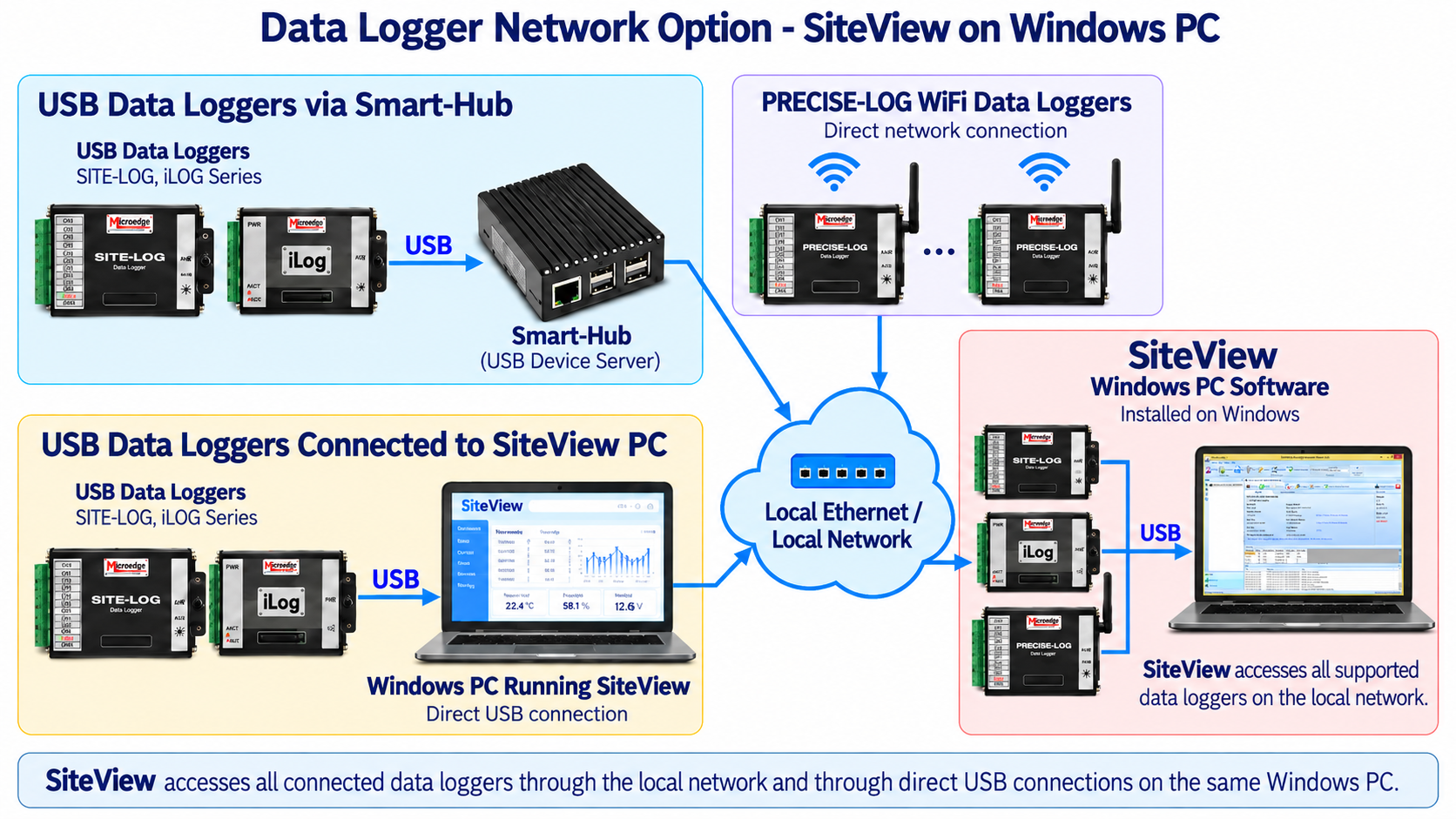
SiteView can access the PL-HW through either:
- Direct USB connection
- WiFi / local network connection
Alarm Functions
The PL-HW provides configurable alarm functions for temperature- and resistance-monitoring applications.
Each channel supports two programmable alarm thresholds.
The onboard tri-color status LED provides visual indication of:
- Normal sampling
- Alarm condition
- Low battery
The LED can be disabled to reduce power consumption.
Direct Network Access
Unlike USB-only data loggers, the PL-HW includes its own WiFi network interface.
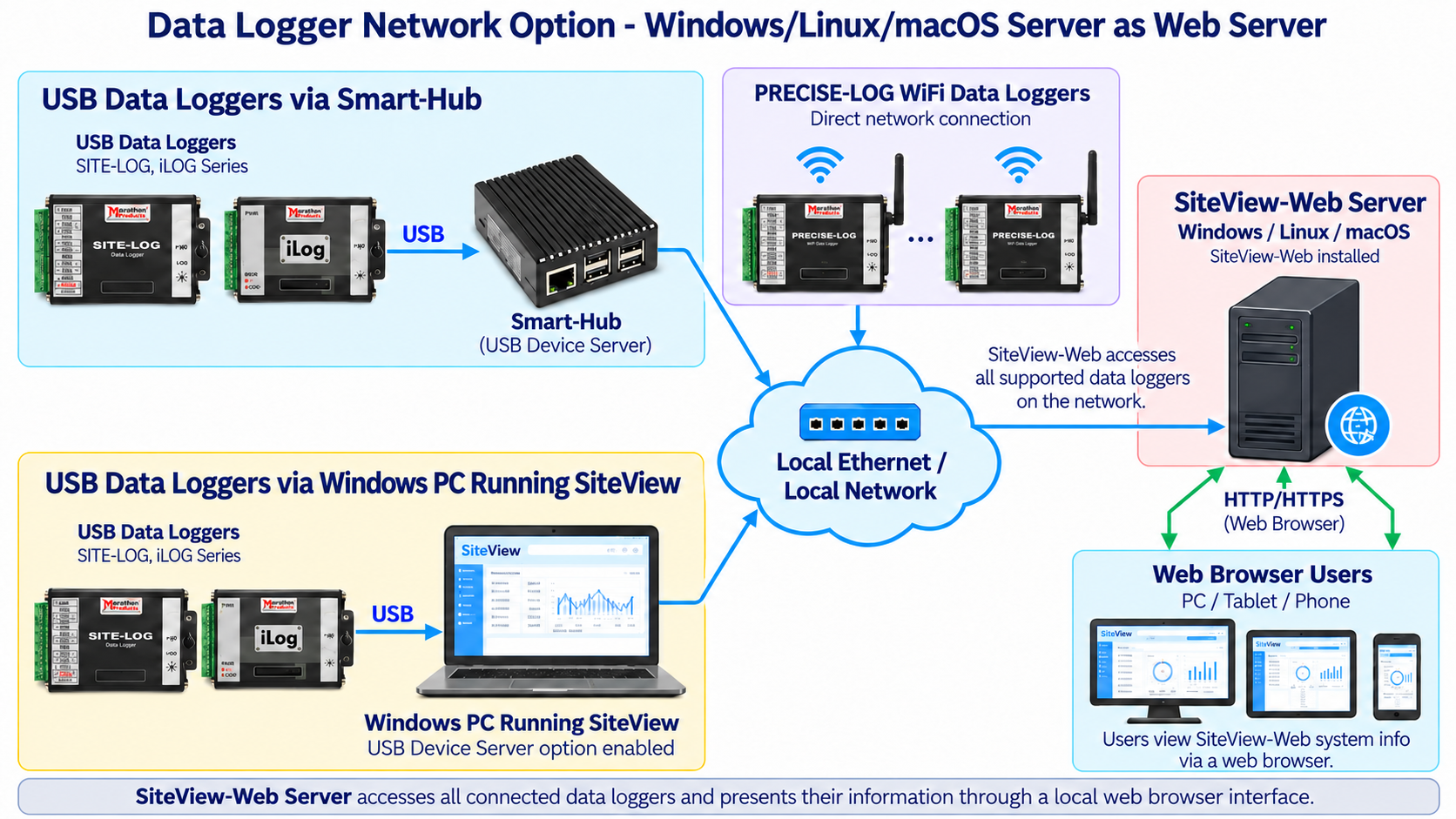
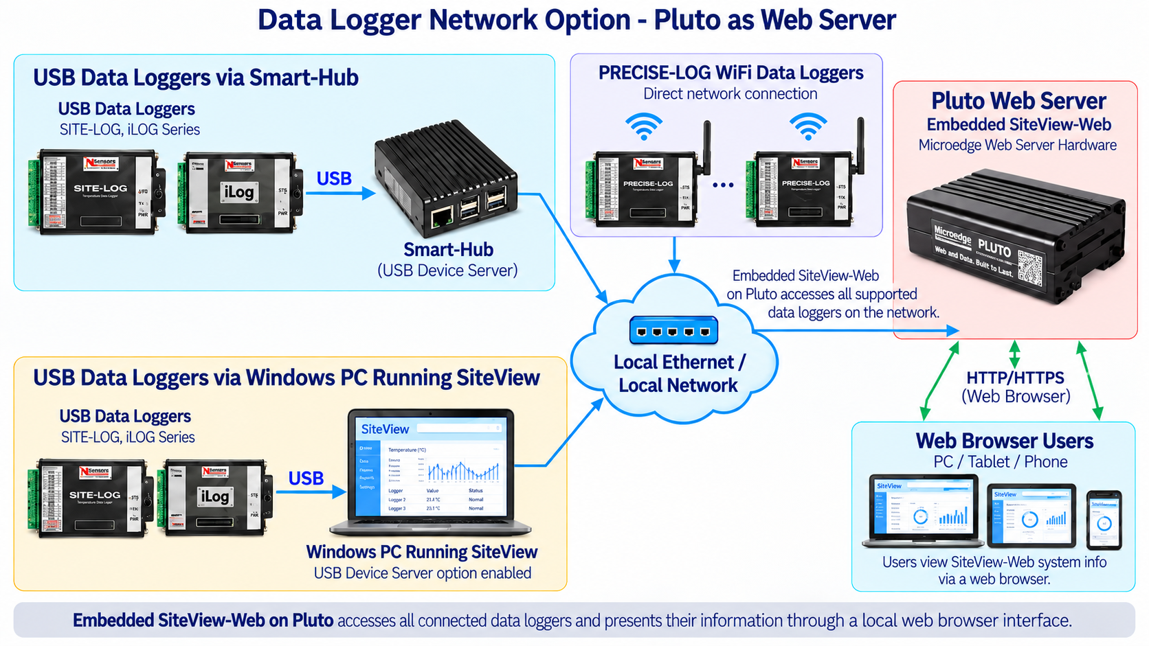
Once connected to a local wireless network, the PL-HW can be accessed directly by supported Microedge software without requiring Smart-Hub.
Supported applications include:
- SiteView
- SiteView-Web
- SiteView SDK
- Pluto
This makes PL-HW suitable for distributed temperature-monitoring installations where loggers may be located away from the monitoring computer.
Modbus TCP Server
The PL-HW can operate directly as a Modbus TCP server.
A compatible Modbus TCP master/client can access the logger over the network and read:
- Real-time channel readings through Input Registers
- Logger configuration and channel information through Holding Registers
Modbus TCP support is available with PRECISE-LOG firmware version 2.06 or later.
This allows the PL-HW to integrate directly with:
- PLCs
- HMIs
- SCADA systems
- Building-management systems
- Industrial PCs
- Custom Modbus software
- Other Modbus TCP master devices
Rugged Industrial Design
The PL-HW is housed in a durable aluminum enclosure designed for laboratory, industrial, and field applications.
Its operating environment is:
−40°C to +70°C (−40°F to +158°F)
and:
0–95% RH, non-condensing.
KEY FEATURES
8 External Thermistor / Resistance Channels
Provides multi-point measurement using independently configurable external inputs.10 kΩ NTC Thermistor Support
Optimized for temperature measurement with compatible 10 kΩ NTC thermistors.Resistance Measurement
Supports resistance-based measurement for compatible resistive sensors and custom equations.16-Bit Data Resolution
Provides 0.0018% measurement resolution.8 MB Non-Volatile Flash Memory
Stores approximately 4 million readings for long-term standalone recording.1 Second to 12 Hour Sampling
Wide programmable sampling interval selection for short-term testing and long-term monitoring.Long Battery Life
Up to approximately 10 years at a 1-minute sampling interval in standalone operation.USB Communication
Provides direct local communication with SiteView.Built-In WiFi
Connects directly to a wireless network without requiring an external USB Device Server.Remote Network Access
Supports SiteView, SiteView-Web, SiteView SDK, and Pluto over the network.Direct Modbus TCP Support
PL-HW can operate as a Modbus TCP server for direct integration with PLC, HMI, SCADA, and third-party systems.Programmable Alarm Thresholds
Two configurable alarm thresholds are available for each channel.Flexible Logging Modes
Supports immediate start, delayed start, field push-button activation, stop-on-full, and FIFO operation.Rugged Aluminum Enclosure
TYPICAL APPLICATIONS
The PL-HW is suitable for:
- Multi-point temperature monitoring
- 10 kΩ NTC thermistor monitoring
- Industrial process temperature monitoring
- Laboratory testing
- Research
- Product validation
- Environmental chambers
- HVAC monitoring
- Equipment temperature monitoring
- Manufacturing processes
- Remote temperature monitoring
- Distributed wireless temperature measurement
- Resistance measurement
- Modbus TCP temperature monitoring
- PLC / SCADA integration
- Long-term unattended temperature logging
DOCUMENTS
- PRECISE-LOG Thermistor Data Logger Specifications
- SiteView Specifications
- PRECISE-LOG WiFi Configuration
| General | |
|---|---|
| Product Name | PL-HW PRECISE-LOG 8-Channel WiFi Thermistor Data Logger |
| Model | PL-HW |
| Inputs | |
| Connection | Pluggable terminal block for 8 external channels |
| Channels | 8 external thermistor / resistance inputs |
| Resolution | 0.0018% |
| Accuracy | ±0.2°C from 0°C to 70°C |
| Alarms | |
| Channel Alarm Thresholds | Two programmable alarm thresholds per channel |
| Alarm Indicator | Status LED flashes red during sampling when an alarm condition is active |
| On-board Memory | |
| Flash Memory | 8 MB (4MB readings) non-volatile flash memory |
| Data Retention | More than 20 years. |
| Memory-Full Options | Stop logging or FIFO mode |
| Sampling and Logging | |
| Sampling Interval | Programmable from 1 second to 12 hours |
| Logging Modes | Stop when memory is full or continue in FIFO mode |
| Logging Activation | Immediate start, delayed start, or field push-button activation |
| Communications | |
| USB Interface | Mini-USB-B |
| Included USB Cable | USB-A to Mini-USB-B |
| WiFi | Built-in |
| WiFi Standard | IEEE 802.11b/g/n |
| Frequency | 2.412–2.484 GHz |
| Transmit Power | 11–18 dBm |
| Receive Sensitivity | −82 to −93 dBm |
| Security | WEP / WPA-PSK / WPA2-PSK |
| Encryption | WEP64 / WEP128 / TKIP / AES |
| Encryption | WEP64 / WEP128 / TKIP / AES |
| Communication Rate | 115200 bps |
| WiFi Enable/Disable | Configurable through SiteView |
| Modbus TCP | Supported |
| Battery and Power | |
| Internal Battery | Built-in 3.6 V lithium battery |
| Battery Life | Up to approximately 10 years at a 1-minute sampling interval in standalone mode |
| WiFi Power Adapter | USB 5 VDC wall power adapter included |
| Software | |
| Software | SiteView (Sold separately) |
| Functions | Configuration, downloading, plotting, real-time monitoring, custom calibration and custom equations |
| Local Communication | USB |
| Remote Communication | WiFi / local network |
| Computer Requirement | 1.0 GHz or faster processor; 1 GB RAM or higher; 10 GB available storage or higher |
| Required Interface | At least one available USB port |
| Physical Specifications | |
| Enclosure Material | Aluminum |
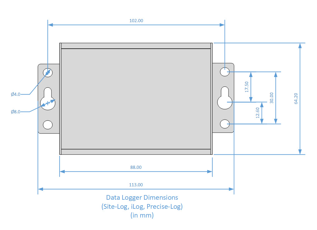
| Dimension | 88 X 64.2 X 24 mm (3.46 X 2.53 X 0.95 inches) |
| Weight | 200g |
| Mounting | Integrated holes for wall or equipment mounting |
| LED Indicators | |
| The tri-color status LED can be disabled to reduce power consumption. | |
| Green Indication | Normal sampling |
| Red Indication | Alarm condition |
| Amber Indication | Low battery |
| Operating Environment | |
| Operating Temperature | -40 ~ +70 °C (-40 °F ~ 158 °F) |
| Operating Humidity | 0 ~ 95% RH, non-condensing |
| Clock Accuracy | ±1 mintue per month |
| Approval | CE, FCC |
Logger Memory Capacity
| Sampling Interval | Enabled Channel | Logging Capacity |
|---|---|---|
| 1 minute | 1 | 8 years |
| 1 minute | 2 | 4 years |
| 1 minute | 8 | 1 year |
| 10 seconds | 1 | 485 days |
| 10 seconds | 2 | 242 days |
| 10 seconds | 8 | 60 days |
| 1 second | 1 | 48 days |
| 1 second | 2 | 24 days |
| 1 second | 8 | 6 days |
Modbus TCP support was added to the PRECISE-LOG series with firmware version 2.06. A Modbus TCP master/client can read supported Input Registers and Holding Registers directly from a PRECISE-LOG data logger over a network connection.
The following specifications list the Modbus commands and registers supported by the PL-HW data logger.
Input Registers:
An Input Register stores a 16-bit integer for a channel’s real-time reading. To read one or more 16-bit Input register data, use function code 4.
| Register | Description | Type | Range |
|---|---|---|---|
| 0 | CH0 Value | Unsigned Integer | 0 - 65535 |
| 1 | CH1 Value | Unsigned Integer | 0 - 65535 |
| 2 | CH2 Value | Unsigned Integer | 0 - 65535 |
| 3 | CH3 Value | Unsigned Integer | 0 - 65535 |
| 4 | CH4 Value | Unsigned Integer | 0 - 65535 |
| 5 | CH5 Value | Unsigned Integer | 0 - 65535 |
| 6 | CH6 Value | Unsigned Integer | 0 - 65535 |
| 7 | CH7 Value | Unsigned Integer | 0 - 65535 |
Example:
To read CH2, CH3 and CH4's real-time values, a Modbus master device sends in the following command:
| Data(HEX) | Description | Note |
|---|---|---|
| 0001 | Transaction identifier | Fixed 2-byte value |
| 0000 | Protocol identifier | Fixed 2-byte value |
| 0006 | Length(6 bytes are followed) | 2-byte value |
| 01 | The device address | 1-byte value, don't care |
| 04 | Function Code (read Input Register) | 1-byte value |
| 0002 | First register's address | 2-byte value |
| 0003 | The number of required registers (read 3 registers 0002 to 0004) | 2-byte value |
Holding Registers:
A Holding Register stores a 16-bit integer indicating a setting for the data logger. To read one or more 16-bit Holding Register data, use function code 3.
| Register | Description | Type | Range/Equation |
|---|---|---|---|
| 0 | Sample Interval | 0: below 1 second >=1: sample interval in second |
0 - 65535 seconds |
| 1 | Device Operating Mode | 0: logging stopped 1: logger is logging data |
|
| X0 | CHX-1 Type | Thermistor | |
| X1 | CHX-1 Enabled | 0:disabled 1:enabled |
If a channel is disabled, the reading is unknown |
| X2 | CHX-1 Equation | 0: Temperature | Range: -40 - + 70 ℃ / -40 to +158 ℉ Equation for Metrics: O = 110 * I / 65535 – 40 Equation for Imperial: O = 198 * I / 65535 – 40 |
| 1: Resistance | Range: 0 – 350000 Ohm Equation: O = 350000 * I / 65535 |
||
| 2: Linear | O = (LRH – LRL) * I / 65535 + LRL Where: LRH is Linear Range high value LRL is Linear Range low value You can get those values from SiteView |
Where X = 1,2,3,4,5,6,7,8
O = Output, I = Input Register Value
Example:
To read CH3's equation, a Modbus master device sends in the following command:
| Data(HEX) | Description | Note |
|---|---|---|
| 0001 | Transaction identifier | Fixed 2-byte value |
| 0000 | Protocol identifier | Fixed 2-byte value |
| 0006 | Length(6 bytes are followed) | 2-byte value |
| 01 | The device address | 1-byte value, don't care |
| 03 | Function Code (read Holding Register) | 1-byte value |
| 002A | First register's address (42 is 2A in HEX) | 2-byte value |
| 0001 | The number of required registers (read 1 registers 002A) | 2-byte value |
Note:
- Modbus feature was added to firmware version 2.06 or above.
To upgrade a data logger's firmware please refer to this link: How can I upgrade logger firmware?
- The age of an Input Register data is based on the Modbus request rate.
A request of Input Register data will initiate the sampling process and the new data will be available upon the next request.
Resources:
LPTH-1 SITE-LOG Thermistor and Temperature Data Logger
The LPTH-1 SITE-LOG is a rugged 7-channel thermistor data logger designed for multi-point temperatur..
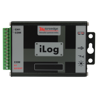
iTH-10 iLOG Thermistor and Temperature Data Logger
iLog Thermistor Data Logger is low cost, high accuracy, battery powered, stand-alone external thermi..
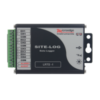
LRTD SITE-LOG Resistance Temperature Data Logger
The LRTD SITE-LOG is a rugged 4-channel RTD temperature data logger designed for multi-point tempera..
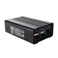
Pluto - Web Server Hardware
Pluto is a Web Server hardware box providing a data logging system that can be accessed remotely fro..
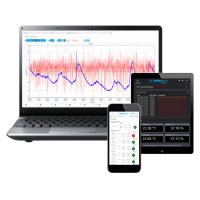
SiteView-Web
SiteView-Web is web server software that can run under most popular operating systems including Win..
PL-H PRECISE-LOG Thermistor Data Logger
PL-H is an 8-channel, battery powered, standalone thermistor data logger. The logger records eight e..