

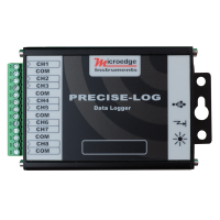
PL-TW PRECISE-LOG Thermocouple Data Logger
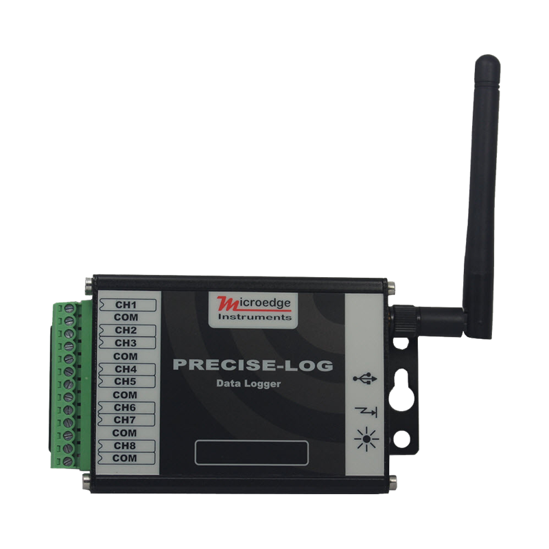
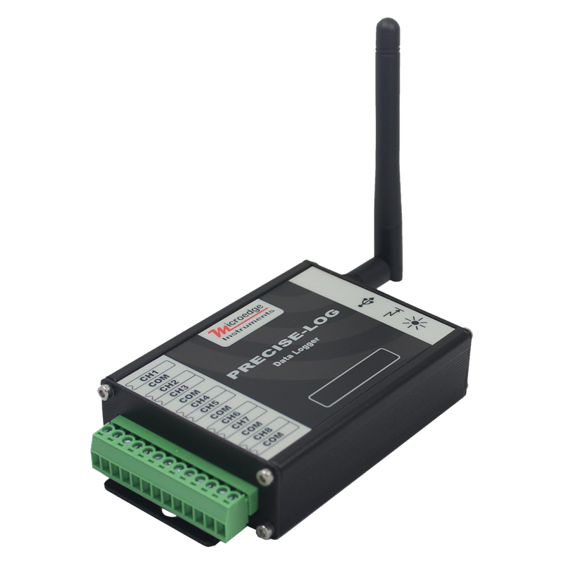
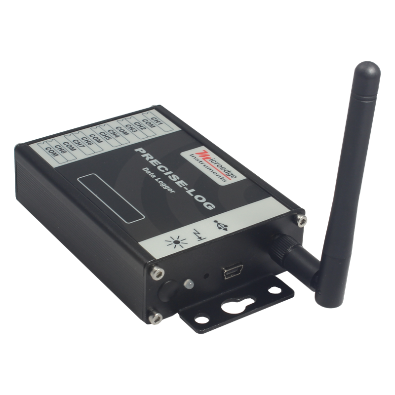
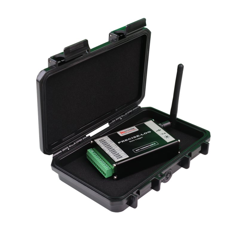
The PRECISE-LOG PL-TW is an 8-channel, battery-powered, standalone and WiFi-enabled thermocouple data logger designed for industrial, laboratory, research, testing, and remote temperature-monitoring applications.
The logger provides:
- 8 external thermocouple input channels
- 1 onboard thermistor temperature channel
- Built-in cold-junction compensation
- USB and WiFi communication
- 8 MB non-volatile flash memory
- Direct Modbus TCP support
Each external channel can be independently configured for the required thermocouple type and input range.
The onboard thermistor measures ambient temperature and provides cold-junction compensation for accurate thermocouple measurement.
Because WiFi is built directly into the PL-TW, the logger can connect to a local wireless network without requiring Smart-Hub or another external USB Device Server.
Multi-Channel Thermocouple Measurement
The PL-TW provides eight external thermocouple channels for multi-point temperature monitoring.
Two programmable voltage ranges are available:
- −8 mV to +73 mV
- −2 mV to +18 mV
Depending on the selected range, the logger supports thermocouple types:
- B
- C
- E
- J
- K
- N
- R
- S
- T
Each channel can be independently enabled and configured through SiteView.
This allows different thermocouple types or temperature ranges to be used within the same data-logging system.
Cold-Junction Compensation
The PL-TW includes an onboard thermistor that measures ambient temperature from:
−40°C to +70°C (−40°F to +158°F)
The onboard temperature channel is used for cold-junction compensation, allowing the logger to compensate thermocouple measurements for the temperature at the logger terminals.
The onboard thermistor accuracy is:
±0.2°C from 0°C to 70°C.
High-Resolution Data Logging
The PL-TW uses a 16-bit analog-to-digital converter with a measurement resolution of:
0.0018%
This provides high-resolution temperature measurement for laboratory, industrial, research, validation, and testing applications.
Sampling intervals are programmable from:
1 second to 12 hours.
Standalone Operation and Long-Term Recording
The PL-TW operates independently after configuration and stores measurements in 8 MB of non-volatile flash memory.
The memory provides storage for approximately 4 million readings and retains recorded data for more than 20 years.
Logging can be configured for:
- Immediate start
- Delayed start
- Field push-button activation
When memory becomes full, the logger can either:
- Stop recording, or
- Continue recording in FIFO mode
The built-in 3.6 V lithium battery provides up to approximately 10 years of operation at a 1-minute sampling interval in standalone mode, depending on operating conditions and configuration.
USB and WiFi Communication
The PL-TW provides both USB and WiFi communication.
USB can be used for direct local communication with SiteView.
The built-in WiFi interface allows the logger to connect directly to a local wireless network for remote access.
Supported WiFi specifications include:
- IEEE 802.11b/g/n
- 2.412–2.484 GHz frequency range
- WEP
- WPA-PSK
- WPA2-PSK
- WEP64 / WEP128
- TKIP / AES encryption
WiFi can be enabled or disabled through SiteView.
SiteView Software
The PL-TW is supported by SiteView software.
SiteView provides tools for:
- Configuring thermocouple channels
- Selecting thermocouple types
- Selecting input ranges
- Configuring logging sessions
- Downloading recorded data
- Viewing real-time temperatures
- Displaying graphs and tables
- Configuring alarm thresholds
- Applying custom calibration
- Applying custom equations
- Exporting and analyzing recorded data
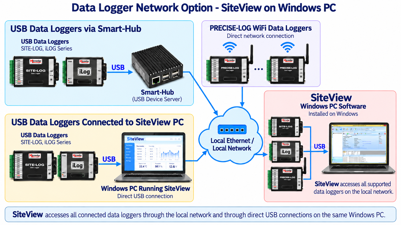
SiteView can access the PL-TW through either:
- Direct USB connection
- WiFi / local network connection
Alarm Functions
The PL-TW provides configurable alarm functions for temperature-monitoring applications.
Each channel supports two programmable alarm thresholds.
The onboard tri-color status LED provides visual indication of:
- Normal sampling
- Alarm condition
- Low battery
The LED can be disabled to reduce power consumption.
Direct Network Access
Unlike USB-only data loggers, the PL-TW includes its own WiFi network interface.
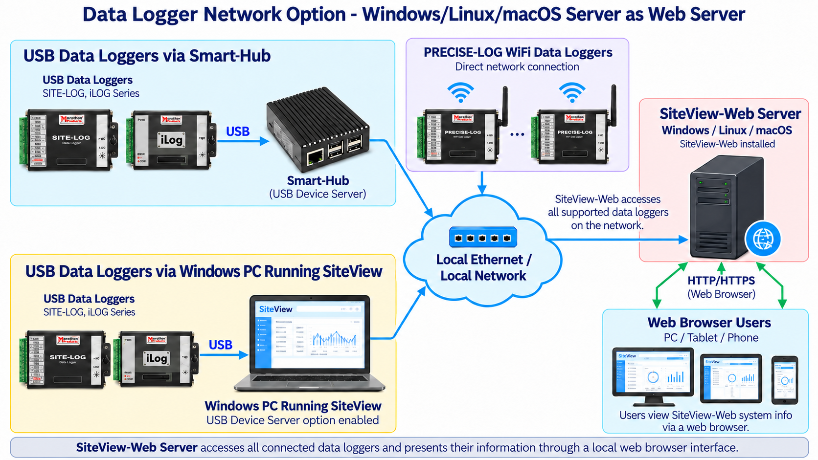
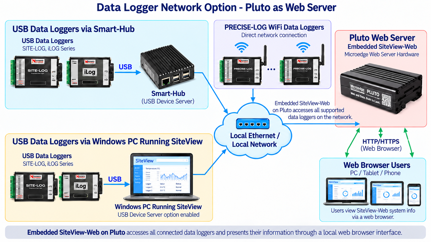
Once connected to a local wireless network, the PL-TW can be accessed directly by supported Microedge software without requiring Smart-Hub.
Supported applications include:
- SiteView
- SiteView-Web
- SiteView SDK
- Pluto
This makes PL-TW suitable for distributed temperature-monitoring installations where loggers may be located away from the monitoring computer.
Modbus TCP Server
The PL-TW can operate directly as a Modbus TCP server.
A compatible Modbus TCP master/client can access the logger over the network and read:
- Real-time channel readings through Input Registers
- Logger configuration and channel information through Holding Registers
Modbus TCP support was added with PRECISE-LOG firmware version 2.06 or later.
This allows the PL-TW to integrate directly with:
- PLCs
- HMIs
- SCADA systems
- Building-management systems
- Industrial PCs
- Custom Modbus software
- Other Modbus TCP master devices
No Smart-Hub is required for PL-TW's direct Modbus TCP operation.
Rugged Industrial Design
The PL-TW is housed in a durable aluminum enclosure designed for laboratory, industrial, and field applications.
Its operating environment is:
−40°C to +70°C (−40°F to +158°F)
and:
0–95% RH, non-condensing.
KEY FEATURES
8 External Thermocouple Channels
Provides multi-point temperature measurement using independently configurable thermocouple inputs.Onboard Temperature Channel
Built-in thermistor monitors ambient temperature and provides cold-junction compensation.Multiple Thermocouple Types
Supports B, C, E, J, K, N, R, S, and T thermocouples depending on the selected input range.Two Programmable Input Ranges
Supports −8 to +73 mV and −2 to +18 mV ranges.16-Bit Data Resolution
Provides 0.0018% measurement resolution.8 MB Non-Volatile Flash Memory
Stores approximately 4 million readings for long-term standalone recording.1 Second to 12 Hour Sampling
Wide programmable sampling interval selection for both short-term testing and long-term monitoring.Long Battery Life
Up to approximately 10 years at a 1-minute sampling interval in standalone operation.USB Communication
Provides direct local communication with SiteView.Built-In WiFi
Connects directly to a wireless network without requiring an external USB Device Server.Remote Network Access
Supports SiteView, SiteView-Web, SiteView SDK, and Pluto over the network.Direct Modbus TCP Support
PL-TW can operate as a Modbus TCP server for direct integration with PLC, HMI, SCADA, and third-party systems.Programmable Alarm Thresholds
Two configurable alarm thresholds are available for each channel.Flexible Logging Modes
Supports immediate start, delayed start, field push-button activation, stop-on-full, and FIFO operation.Rugged Aluminum Enclosure
TYPICAL APPLICATIONS
The PL-TW is suitable for:
- Multi-point temperature monitoring
- Industrial process temperature monitoring
- Laboratory testing
- Research
- Product validation
- Environmental chambers
- Equipment testing
- Oven and furnace monitoring
- HVAC temperature monitoring
- Manufacturing processes
- Remote temperature monitoring
- Distributed wireless temperature measurement
- Modbus TCP temperature monitoring
- PLC / SCADA integration
- Long-term unattended temperature logging
DOCUMENTS
- PRECISE-LOG Thermocouple Data Logger Specifications
- SiteView Specifications
- PRECISE-LOG WiFi Configuration
| General | |
|---|---|
| Product Name | PRECISE-LOG Thermocouple Data Logger |
| Model | PL-TW |
| External Channels | 8 thermocouple channels |
| Internal Channel | 1 onboard thermistor |
| Inputs | |
| Connection | Pluggable terminal block for 8 external channels |
| External Inputs | 8 thermocouple channels |
| Onboard Temperature | −40°C to +70°C (-40°F ~ 158°F) |
| Programmable Range 1 | −8 mV to +73 mV |
| Programmable Range 2 | −2 mV to +18 mV |
| Resolution | 0.0018% |
| Thermistor Accuracy | ±0.2°C from 0°C to 70°C |
| Thermocouple Accuracy | ±0.1% to ±0.2% plus thermocouple accuracy |
| Cold-Junction Compensation | Onboard thermistor |
| Overvoltage Protection | Up to ±20 VDC |
| Alarms | |
| Channel Alarm Thresholds | Two programmable alarm thresholds per channel |
| Alarm Indicator | Status LED flashes red during sampling when an alarm condition is active |
| On-board Memory | |
| Flash Memory | 8 MB (4MB readings) non-volatile flash memory |
| Data Retention | More than 20 years. |
| Memory-Full Options | Stop logging or FIFO mode |
| Sampling and Logging | |
| Sampling Interval | Programmable from 1 second to 12 hours |
| Logging Modes | Stop when memory is full or continue in FIFO mode |
| Logging Activation | Immediate start, delayed start, or field push-button activation |
| Communications | |
| USB Interface | Mini-USB-B |
| Included USB Cable | USB-A to Mini-USB-B |
| WiFi | Built-in |
| WiFi Standard | IEEE 802.11b/g/n |
| Frequency | 2.412–2.484 GHz |
| Transmit Power | 11–18 dBm |
| Receive Sensitivity | −82 to −93 dBm |
| Security | WEP / WPA-PSK / WPA2-PSK |
| Encryption | WEP64 / WEP128 / TKIP / AES |
| Encryption | WEP64 / WEP128 / TKIP / AES |
| Communication Rate | 115200 bps |
| WiFi Enable/Disable | Configurable through SiteView |
| Modbus TCP | Supported |
| Battery and Power | |
| Internal Battery | Built-in 3.6 V lithium battery |
| Battery Life | Up to approximately 10 years at a 1-minute sampling interval in standalone mode |
| WiFi Power Adapter | USB 5 VDC wall power adapter included |
| Software | |
| Software | SiteView (Sold separately) |
| Functions | Configuration, downloading, plotting, real-time monitoring, custom calibration and custom equations |
| Local Communication | USB |
| Remote Communication | WiFi / local network |
| Computer Requirement | 1.0 GHz or faster processor; 1 GB RAM or higher; 10 GB available storage or higher |
| Required Interface | At least one available USB port |
| Physical Specifications | |
| Enclosure Material | Aluminum |
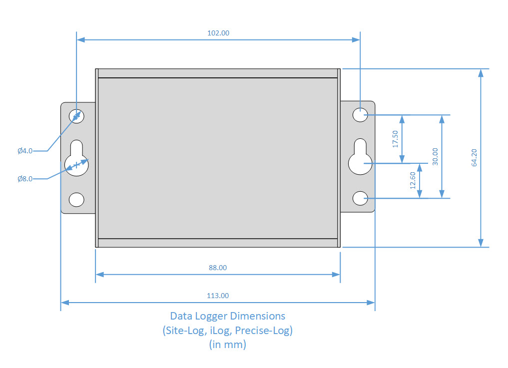
| Dimension | 88 X 64.2 X 24 mm (3.46 X 2.53 X 0.95 inches) |
| Weight | 200g |
| Mounting | Integrated holes for wall or equipment mounting |
| LED Indicators | |
| The tri-color status LED can be disabled to reduce power consumption. | |
| Green Indication | Normal sampling |
| Red Indication | Alarm condition |
| Amber Indication | Low battery |
| Operating Environment | |
| Operating Temperature | -40 ~ +70 °C (-40 °F ~ 158 °F) |
| Operating Humidity | 0 ~ 95% RH, non-condensing |
| Clock Accuracy | ±1 mintue per month |
| Approval | CE, FCC |
Logger Memory Capacity
| Sampling Interval | Enabled Channel | Logging Capacity |
|---|---|---|
| 1 minute | 1 | 8 years |
| 1 minute | 2 | 4 years |
| 1 minute | 8 | 1 year |
| 10 seconds | 1 | 485 days |
| 10 seconds | 2 | 242 days |
| 10 seconds | 8 | 60 days |
| 1 second | 1 | 48 days |
| 1 second | 2 | 24 days |
| 1 second | 8 | 6 days |
Programmable Channel Range Specifications:
| Range: -8mV ~ +73mV Accuracy: ±0.1% (0.08 mV)@ 25°C + Temperature Compensation Accuracy | |||
|---|---|---|---|
| Thermocouple Type | Temperature Range (°C) | Resolution (°C) | Accuracy (°C) |
| Type E | -171 to +955 | 0.02 | 0.56 |
| Type J | -205 to +1200 | 0.027 | 0.73 |
| Type K | -270 to +1372 | 0.04 | 1.07 |
| Type N | -270 to +1300 | 0.045 | 1.21 |
| Type T | -270 to +400 | 0.037 | 1.00 |
| Type C | 0 to 2320 | 0.1 | 2.5 |
| Type S | -50 to 1768 | 0.04 | 3.85 |
| Range: -2mV ~ +18mV Accuracy: ±0.15% (0.03 mV) @ 25°C + Temperature Compensation Accuracy | |||
| Type E | -35 to 260 | 0.005 | 0.45 |
| Type J | -40 to 330 | 0.0062 | 0.56 |
| Type K | -53 to 437 | 0.0082 | 0.74 |
| Type N | -81 to 532 | 0.01 | 0.92 |
| Type T | -55 to 353 | 0.008 | 0.62 |
| Type B | 0 to 1820 | 0.03 | 3.95 |
| Type R | -50 to 1539 | 0.026 | 2.62 |
| Type S | -50 to 1704 | 0.03 | 2.9 |
| Type C | 0 to 986 | 0.0164 | 1.65 |
Modbus TCP support was added to the PRECISE-LOG series with firmware version 2.06. A Modbus TCP master/client can read supported Input Registers and Holding Registers directly from a PRECISE-LOG data logger over a network connection.
The following specifications list the Modbus commands and registers supported by the PL-TW data logger.
Input Registers:
An Input Register stores a 16-bit integer for a channel’s real-time reading. To read one or more 16-bit Input register data, use function code 4.
| Register | Description | Type | Range |
|---|---|---|---|
| 0 | CH0 Value | Unsigned Integer | 0 - 65535 |
| 1 | CH1 Value | Unsigned Integer | 0 - 65535 |
| 2 | CH2 Value | Unsigned Integer | 0 - 65535 |
| 3 | CH3 Value | Unsigned Integer | 0 - 65535 |
| 4 | CH4 Value | Unsigned Integer | 0 - 65535 |
| 5 | CH5 Value | Unsigned Integer | 0 - 65535 |
| 6 | CH6 Value | Unsigned Integer | 0 - 65535 |
| 7 | CH7 Value | Unsigned Integer | 0 - 65535 |
| 8 | CH8 Value | Unsigned Integer | 0 - 65535 |
Example:
To read CH2, CH3 and CH4's real-time values, a Modbus master device sends in the following command:
| Data(HEX) | Description | Note |
|---|---|---|
| 0001 | Transaction identifier | Fixed 2-byte value |
| 0000 | Protocol identifier | Fixed 2-byte value |
| 0006 | Length(6 bytes are followed) | 2-byte value |
| 01 | The device address | 1-byte value, don't care |
| 04 | Function Code (read Input Register) | 1-byte value |
| 0002 | First register's address | 2-byte value |
| 0003 | The number of required registers (read 3 registers 0002 to 0004) | 2-byte value |
Holding Registers:
A Holding Register stores a 16-bit integer indicating a setting for the data logger. To read one or more 16-bit Holding Register data, use function code 3.
| Register | Description | Type | Range/Equation |
|---|---|---|---|
| 0 | Sample Interval | 0: below 1 second >=1: sample interval in second |
0 - 65535 seconds |
| 1 | Device Operating Mode | 0: logging stopped 1: logger is logging data |
|
| 10 | CH0 Type | 0:thermistor | |
| 11 | CH0 Enabled | 0:disabled 1:enabled |
If a channel is disabled, the reading is unknown |
| 12 | CH0 Equation | 0: thermistor | Range: -40 to + 70 ℃ / -40 to 158 ℉ Equation for Metrics: O = 110 * I / 65535 - 40 Equation for Imperial: O = 198 * I / 65535 - 40 |
| X0 | CHX-1 Type | 0: Wide Range | -8 to + 74 mV |
| 1: Narrow Range | -2 to + 18 mV | ||
| X1 | CHX-1 Enabled | 0: Disabled 1: Enabled |
If a channel is disabled the reading is unknown |
| X2 | CHX-1 Equation | 0: Wide-Range Voltage | Voltage Equation (mV) O = 81 * I / 65535 - 8 |
| 1: Wide-Range TC E | -171 to + 955 ℃ / -275.8 to + 1751 ℉ Temperature Equation (Metrics): O = 1126 * I / 65535 – 171 Temperature Equation (Imperial): O = 2026.8 * I / 65535 – 275.8 |
||
| 2: Wide-Range TC J | -205 to + 1200 ℃ / -337 to + 2192 ℉ Temperature Equation (Metrics): O = 1405 * I / 65535 – 205 Temperature Equation (Imperial): O = 2529 * I / 65535 - 337 |
||
| 3: Wide-Range TC K | -270 to + 1372 ℃ / -454 to + 2501.6 ℉ Temperature Equation (Metrics): O = 1642 * I / 65535 -270 Temperature Equation (Imperial): O = 2955.6 * I / 65535 – 454 |
||
| 4: Wide-Range TC N | -270 to 1300 °C / -454 to 2372 ℉ Temperature Equation (Metrics): O = 1570 * I / 65535 - 270 Temperature Equation (Imperial): O = 2826 * I / 65535 - 454 |
||
| 5: Wide-Range TC T | -270 to + 400 °C / -454 to +752 ℉ Temperature Equation (Metrics): O = 670 * I / 65535 - 270 Temperature Equation (Imperial): O = 1206 * I / 65535 - 454 |
||
| 6: Narrow-Range Voltage | Voltage Equation (mV): O = 20 * I / 65535 – 2 |
||
| 7: Narrow-Range TC E | -35 to + 260 °C / -31 to +500 ℉ Temperature Equation (Metrics): O = 295 * I / 65535 - 35 Temperature Equation (Imperial): O = 531 * I / 65535 - 31 |
||
| 8: Narrow-Range TC J | -40 to +330 °C / -40 to +626 ℉ Temperature Equation (Metrics): O = 370 * I / 65535 -40 Temperature Equation (Imperial): O = 666 * I / 65535 - 40 |
||
| 9: Narrow-Range TC K | -53 to +437 °C / -63.4 to +818.6 ℉ Temperature Equation (Metrics): O = 490 * I / 65535 - 53 Temperature Equation (Imperial): O = 882 * I / 65535 - 63.4 |
||
| 10: Narrow-Range TC N | -81 to +532 °C / -113.8 to +989.6 ℉ Temperature Equation (Metrics): O = 613 * I / 65535 - 81 Temperature Equation (Imperial): O = 1103.4 * I / 65535 - 113.8 |
||
| 11: Narrow-Range TC T | -55 to +353 °C / -67 to +667.4 ℉ Temperature Equation (Metrics): O = 408 * I / 65535 - 55 Temperature Equation (Imperial): O = 734.4 * I / 65535 - 67 |
||
| 12: Narrow-Range TC B | 0 to 1820 °C / 32 to +3308 ℉ Temperature Equation (Metrics): O = 1820 * I / 65535 Temperature Equation (Imperial): O = 3276 * I / 65535 + 32 |
||
| 13: Narrow-Range TC R | -50 to +1539 °C / -58 to 2802.2 ℉ Temperature Equation (Metrics): O = 1589 * I / 65535 - 50 Temperature Equation (Imperial): O = 2860.2 * I / 65535 - 58 |
||
| 14: Narrow-Range TC S | -50 to +1704 °C / -58 to 3099.2 ℉ Temperature Equation (Metrics): O = 1754 * I / 65535 - 50 Temperature Equation (Imperial): O = 3157.2 * I / 65535 - 58 |
||
| 15: Linear | O = (LRH – LRL) * I / 65535 + LRL Where: LRH is Linear Range high value LRL is Linear Range low value You can get those values from SiteView |
||
| 16: Wide-Range TC C | 0 to 2320 °C / 32 to 4208 ℉ Temperature Equation (Metrics): O = 2320 * I / 65535 Temperature Equation (Imperial): O = 4176 * I / 65535 + 32 |
||
| 17: Narrow-Range TC C | 0 to 986 °C / 32 to 1806.8 ℉ Temperature Equation (Metrics): O = 986 * I / 65535 Temperature Equation (Imperial): O = 1774.8 * I / 65535 + 32 |
Where X = 2,3,4,5,6,7,8,9
O = Output, I = Input Register Value
Example:
To read CH3's equation, a Modbus master device sends in the following command:
| Data(HEX) | Description | Note |
|---|---|---|
| 0001 | Transaction identifier | Fixed 2-byte value |
| 0000 | Protocol identifier | Fixed 2-byte value |
| 0006 | Length(6 bytes are followed) | 2-byte value |
| 01 | The device address | 1-byte value, don't care |
| 03 | Function Code (read Holding Register) | 1-byte value |
| 002A | First register's address (42 is 2A in HEX) | 2-byte value |
| 0001 | The number of required registers (read 1 registers 002A) | 2-byte value |
Note:
- Modbus feature was added to firmware version 2.06 or above.
To upgrade a data logger's firmware please refer to this link: How can I upgrade logger firmware?
- The age of an Input Register data is based on the Modbus request rate.
A request of Input Register data will initiate the sampling process and the new data will be available upon the next request.
Resources:
LPTM-1 SITE-LOG Thermocouple and Temperature Data Logger
The LPTM-1 SITE-LOG is a rugged 7-channel thermocouple data logger designed for multi-point temperat..
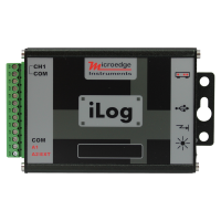
iTC-80 iLOG Thermocouple and Temperature Data Logger
iLog Thermocouple Data Logger is low-cost, high-accuracy, battery-powered, stand-alone thermocouple ..
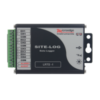
LRTD SITE-LOG Resistance Temperature Data Logger
The LRTD SITE-LOG is a rugged 4-channel RTD temperature data logger designed for multi-point tempera..
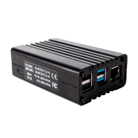
Pluto - Web Server Hardware
Pluto is a Web Server hardware box providing a data logging system that can be accessed remotely fro..
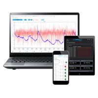
SiteView-Web
SiteView-Web is web server software that can run under most popular operating systems including Win..
PL-T PRECISE-LOG Thermocouple Data Logger
PL-T is an 8-channel, battery powered, standalone thermocouple data logger. The logger records eight..