
MENU
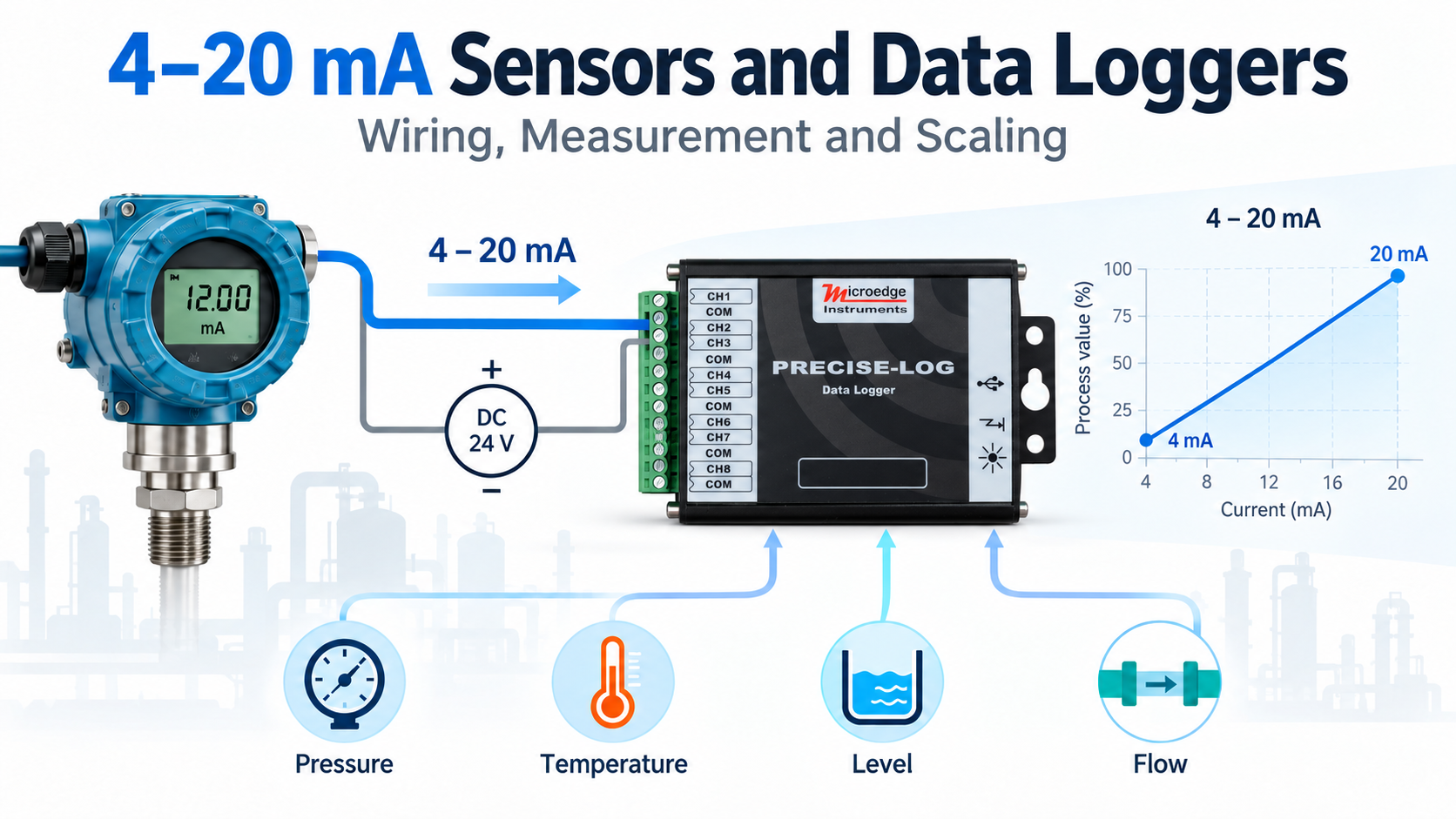
The 4–20 mA current loop is one of the most widely used signal standards in industrial measurement and process monitoring. Pressure, temperature, level, flow, humidity, and many other transmitters commonly provide a 4–20 mA output that can be recorded by a data logger or read by a control system.
This Technical Note explains how a 4–20 mA signal works, how it is connected to a data logger, and how the measured current can be converted into meaningful engineering units.
A 4–20 mA transmitter converts a physical measurement into an electrical current.
Typically:
For example, a pressure transmitter with a range of 0–100 PSI may produce:
| Current | Pressure |
|---|---|
| 4 mA | 0 PSI |
| 8 mA | 25 PSI |
| 12 mA | 50 PSI |
| 16 mA | 75 PSI |
| 20 mA | 100 PSI |
Unlike a voltage signal, a current-loop signal is generally less affected by voltage drop in long cables, making 4–20 mA widely used in industrial environments.
The 4 mA lower limit also provides a useful distinction between a valid minimum reading and certain fault conditions such as an open circuit.
A basic 4–20 mA measurement system includes:
Power Supply → Sensor / Transmitter → Data Logger → Return
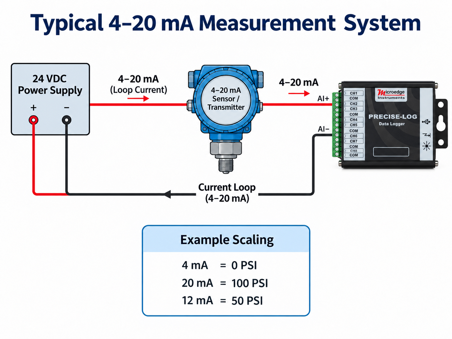
The transmitter controls the amount of current flowing through the loop according to the measured physical quantity.
A data logger measures this loop current and records the value over time.
Depending on the sensor, the transmitter may be:
Always follow the transmitter manufacturer's wiring instructions when connecting the sensor to the measurement system.
Before connecting a 4–20 mA transmitter, check:
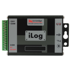
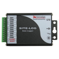
Microedge current-input data loggers support industrial current measurements such as:
Depending on the model, multiple current-loop transmitters can be monitored by a single data logger.
For example:
This allows several industrial sensors to be monitored and recorded by one data logging system.
Many 4–20 mA sensors are two-wire loop-powered transmitters.
In this configuration, the same two wires provide both:
A typical loop may look like:
24 VDC Power Supply → Transmitter → Data Logger Current Input → Power Supply Return
The data logger does not necessarily supply power to the transmitter. An appropriate external power supply may therefore be required.
The transmitter must also have enough available voltage to operate correctly after accounting for the voltage drop across the wiring and other devices in the loop.
Always verify the transmitter's power requirements before installation.
The current value itself is usually not the final information required.
For example, a logger may measure:
12.00 mA
but the user wants to know:
50 PSI
To convert the electrical signal into engineering units, use the sensor manufacturer's specified measurement range.
For a linear 4–20 mA transmitter:
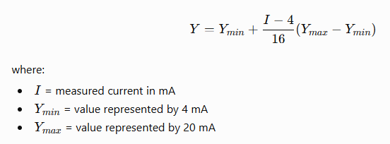
Suppose a pressure transmitter has:
The conversion becomes:
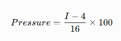
If the logger measures 12 mA:
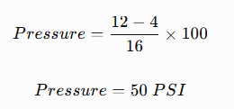
The data logger can therefore display and record pressure directly instead of only storing the current measurement.
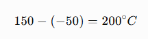
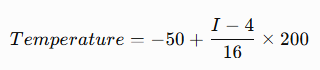
Consider a temperature transmitter configured as:
The total measurement span is:
The conversion equation is:
At 12 mA:
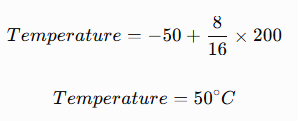
The same principle can be used for pressure, flow, level, temperature, humidity, and other linear transmitters.
Microedge SiteView software allows custom equations to convert electrical input measurements into engineering units.
Instead of displaying only:
12.00 mA
SiteView can apply the appropriate equation and display:
50.0 PSI
Custom equations can be created for sensors such as:
The data can then be viewed, graphed, and exported using the desired engineering units.
Most 4–20 mA measurement problems are related to wiring, power, configuration, or scaling.
Current-loop connections are polarity-sensitive.
Verify the positive and negative connections of the transmitter, power supply, and data logger.
A two-wire transmitter normally requires an external loop power supply.
Without sufficient power, the transmitter cannot generate the expected 4–20 mA signal.
Make sure the data logger channel is configured for the appropriate current range.
For a 4–20 mA transmitter, use the corresponding current measurement configuration.
A broken connection or disconnected wire can interrupt the current loop.
A reading below the expected 4 mA minimum may indicate a wiring or transmitter problem, depending on the equipment being used.
The electrical measurement can be correct while the displayed engineering value is wrong.
Always verify the transmitter's specified:
before creating the conversion equation.
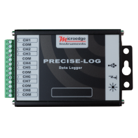
Microedge provides several data loggers for current-loop measurements.
| Model | Current Inputs | Communication |
|---|---|---|
| LPCB-1 | 7 | USB / Smart-Hub |
| LPMB-1 | 3 current + 4 voltage | USB / Smart-Hub |
| PL-C | 8 | USB |
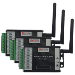
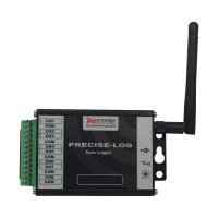
| PL-CW | 8 | USB + WiFi |
Suitable when several current-output sensors need to be monitored with a dedicated multi-channel current data logger.
Useful for systems containing a combination of voltage and current transmitters.
Provides eight current-input channels for standalone and USB-based data logging.
Provides the same type of multi-channel current measurement with built-in WiFi network connectivity and supported Modbus TCP access.
USB-based models can also be connected to a Smart-Hub when Ethernet, RESTful Web API, or Modbus TCP Gateway access is required.
A 4–20 mA current loop provides a reliable and widely used method for connecting industrial sensors to data acquisition systems.
A complete measurement system requires three things to be configured correctly:
Sensor wiring → Current measurement → Engineering-unit conversion
Once the logger measures the current signal, software such as SiteView can convert the value into pressure, temperature, flow, level, or other engineering units and record the measurements for later analysis.
Microedge current-input data loggers can be used for both standalone logging and network-connected monitoring, depending on the communication requirements of the application.


Leave a Comment